Official treatment
1. Turn off the firewall
2. Configure the network card in the control panel PG/**
3. Install your own computer’s official network card driver
Tag: S7-200
Three methods of Siemens PLC serial communication
1, RS485 serial communication
Most of the third-party devices support, Siemens S7 PLC can control serial communication by selecting the free port communication mode. In the simplest case, only send commands (XMT) to send information to third-party devices such as printers or inverters. In any case, it must be programmed by S7 PLC. When the free port mode is selected, the user can control the operation of the communication port by sending an instruction (XMT), a receiving finger (RCV), a transmission interrupt, and receiving an interrupt. Siemens S7200

2, PPI communication
The PPI protocol is the most basic communication method of the S7-200 CPU. It can communicate through its original port (PORT0 or PORT1), which is the default communication method of the S7-200 CPU. PPI is a master-slave protocol communication, and the master-slave station is in a token ring network. The user network can read and write instructions in the CPU, that is, the network read and write instructions are run on the PPI protocol. Therefore, the PPI can only write the program on the main station side, and the network read and write instructions of the slave station have no meaning.
3. MPI communication
MPI communication is a simpler communication method. The MPI network communication rate is 19.2Kbit/s~12Mbit/s. The MPI network supports up to 32 nodes and the maximum communication distance is 50M. The communication distance is long, and the communication distance can also be extended by the repeater, but the repeater also occupies the node. MPI network nodes can usually hang S7-200, human interface, programming devices, and so on.
Siemens PLC S7-200 RS232 wiring method and pin definition?
The communication port on the S7-200 CPU is RS485.
Its pins are defined as follows:
Pin No. Port 0/Port 1
1 chassis grounding
2 logically
3 RS–485 signal B
4 RTS (TTL)
5 logically
6 +5 V, 100Ω series resistor
7 +24V
8 RS–485 signal A
9 10-bit protocol selection (input)
Connector housing chassis ground
The S7-200 can support various types of communication networks. Make a network selection in the “Set PG/PC Interface” properties dialog. A selected network will be used as an interface. The various interfaces that can access these communication networks include:
Multi-master PPI cable
CP communication card
Ethernet communication card
The following steps allow you to select the communication interface for STEP 7–Micro/WIN. See Figure 7-1.
1. Double-click the icon in the Communication Settings window.
2. Select the interface parameters for STEP 7–Micro/WIN.
What are the Siemens PLC communication protocols?
Siemens PLC has 4 categories, dozens of model types, different communication protocols supported by PLC are also different.
The protocols supported by the S7-200 series are: PPI, MPI, PROFIBUS, Ethernet, S7 protocol, AS-INTERFACE, USS, MODBUS, and free port.
The protocols supported by the S7-300\400 series are: MPI, PROFIBUS, ETHERNET, ISO, ISO-ON-TCP, MODBUS, etc.
The same point is the same for the same protocol physical transmission medium. For example, the S7 protocol can use DP and Ethernet as transmission media.
The difference is that each protocol corresponds to a different configuration and program
How to change s7200 communication protocol mpi to ppi
The communication of the S7200 is the PPI protocol.
MPI communication is only used when the S7200 exchanges data with the S7300 and S7400.
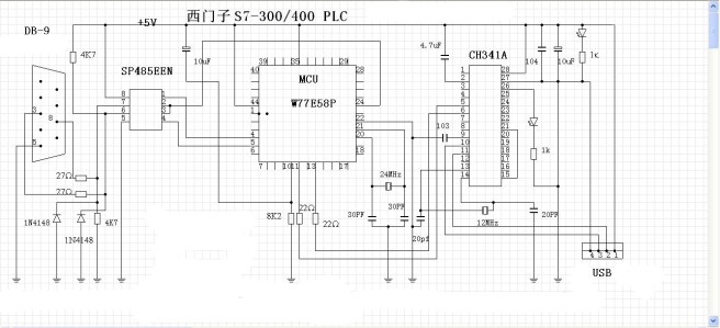
Siemens S7-300/400 PLC USB-MPI cable programming cable circuit diagram
W77E58P is a protocol conversion chip that needs to be programmed and burned to work.
CH341A needs to install USB to serial port driver

Siemens MPI cable production wiring

Where can I change the baud rate of the USB interface?
Siemens PC adapter USB connected to the S7-300 PLC, but the communication is not on, the driver is installed, I remember that after selecting the MPI interface in the Set PG/PC, it depends on the baud rate, it seems to be 1.5M, then in the device management Inside the Ports, find the U port of this line, modify the parameters of this U port, consistent with the properties inside the MPI line to successfully connect, now can not find this U port in Ports. Where can I modify it? ? ?
The PLC connection of Siemens S7-300 and S7-200 does not require setting the baud rate. It can be obtained directly by searching. When connecting, pay attention to the default baud rate and the dialing code on the programming cable.
Siemens programming cable USB-PPI and USB-MPI+
What is the difference between Siemens programming cable USB-PPI and RS232-PPI?
If you can, choose USB. Both are communication cables. The difference is that the current mainstream computer configuration has a USB port, but not necessarily an RS232 port. If you choose RS232, you have to go with the SUB to RS232 converter.
Why can’t I connect PLC and MICWIN programming software with RS232PPI cable after using NETW NETR instruction?
When using the NETWNETR instruction, the port of the PLC is defined as the master. The PPI network is a token network. Once the primary station has a token, the primary station controls the read and write access rights of the network, and other primary stations cannot access the primary station. All MICROWIN cannot communicate properly with the PLC
USB/PPI cable
USB/PPI cable is suitable for the Siemens S7-200 full range of PLCs. It is a programming cable that provides serial connection and RS485 signal conversion and PPI protocol conversion via USB interface.
The driver control running in the computer simulates the USB interface of the computer into a traditional serial port (commonly known as the COM port), thereby using various existing programming software, communication software, and monitoring software. The working power is taken from the USB port and is not powered by the programming port of the PLC. The two-color LED on the converter box indicates the data transmission and reception status. For industrial sites with high interference and easy to damage the communication port, opto-isolated USB/PPI+ programming cable is selected.

USB/PPI cable characteristics and technical indicators:
1. Support USB/PPI operating system: Windows2000/WindowsXP (WinNT4/95/98/Me/DOS is not supported)
2. Support USB/PPI programming software version: STEP7 Micro/WIN V3.2 and above
3. Fully compatible with USB V1.1 and USB CDC V1.1 specifications
4.USB bus power supply, current consumption is about 50mA
5. Baud rate: 9.6kbps standard baud rate automatically adapts
6. Support UART data format
7. Data bits: 8
8. Stop bits: 1, 2
9. Check digit: odd/even/no parity
10. Support the maximum communication distance of 2KM (9600bps)
11. Only one USB programming cable is supported per PC
USB/PPI cable usage:
The USB/PPI programming cable needs to be installed with the USB device driver. These drivers are included on the CD that ships with the product. For the installation method, please refer to the documentation on the driver CD, which will not be described here.
After the driver installation is completed, the COM port corresponding to the USB/PPI programming cable will appear in the device manager of Windows. Simply select the COM port in the programming software or other application software, and the next use is the same as the traditional RS232. The port programming cable is identical. It should be noted here that the programming cable does not support the “USB” option of the local communication port setting in the programming software.
USB/PPI cable long distance communication:
The maximum communication distance between the USB/PPI programming cable and the PLC can reach 2KM (9600bps). In this case, a 120Ω termination resistor should be connected between the 3rd and 8th pins of the RS485 port of the cable (DB9 Male) to eliminate signal reflection. The PFB-G bus isolator is installed on the PLC side, and the communication line adopts a shielded twisted pair with a cross-sectional area of 0.22 mm2 or more. More than 2000 meters distance can be added to the bus to add RS485 repeater to extend the communication distance.
